- Product Overview
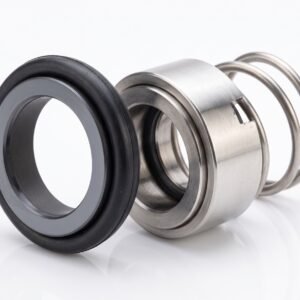
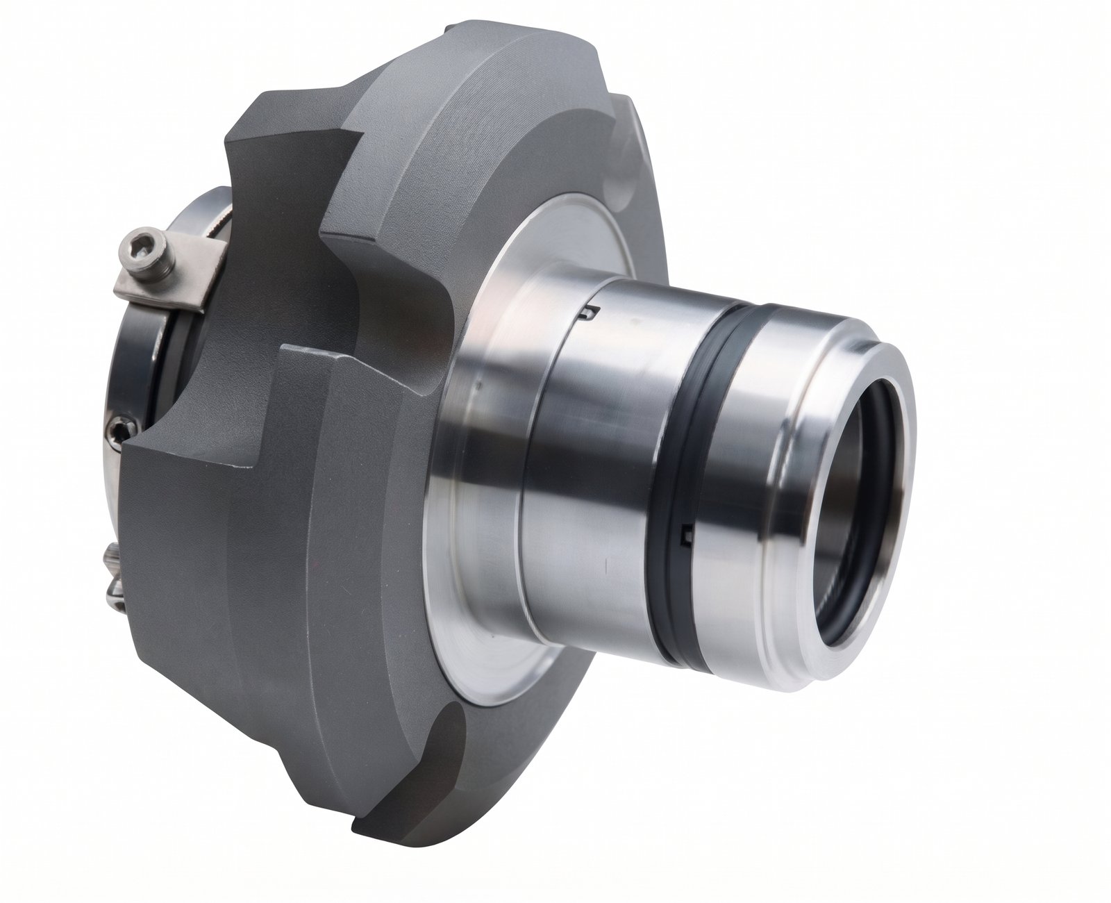
The HJ5620 incorporates inboard and outboard sealing assemblies in a cartridge configuration with a sleeve and gland. The assembled construction simplifies handling and installation compared with separately fitted component seals.
O-rings provide secondary sealing within the pusher arrangement. The inboard and outboard face pairings, elastomer compounds and metal grades must suit the process fluid and the selected buffer or barrier liquid.
For replacement applications, compare the complete assembly with the existing seal, pump installation and auxiliary piping. A matching model reference or nominal shaft size alone does not establish interchangeability.
- Design Features
| Feature | Description |
|---|---|
| Seal Arrangement | Dual mechanical seal with inboard and outboard sealing assemblies |
| Construction | Cartridge assembly incorporating a sleeve and gland |
| Seal Technology | O-ring pusher configuration |
| Installation | Assembled cartridge construction simplifies component handling and positioning |
| Metric Shaft Sizes | Selected configurations from 24 to 140 mm |
| Inch Shaft Sizes | Selected configurations from 1.000 to 5.500 inches |
| Material Selection | Face, secondary seal and metal options for different operating duties |
| Auxiliary System | Buffer or barrier system selected for the specified seal arrangement |
| Replacement Selection | Configuration-specific review for selected John Crane Type 5620 installations |
- Operating Parameters
| Parameter | HJ5620 Supplier-Stated Specification |
|---|---|
| Seal Chamber Temperature | −30 to +205°C / −22 to +401°F |
| Maximum Listed Seal Chamber Pressure | Up to 21 bar / 2.1 MPa / approximately 305 psi; size-specific limits require confirmation |
| Maximum Sliding Velocity | Up to 25 m/s / approximately 82 ft/s |
| Metric Shaft Sizes | 24–140 mm, selected configurations |
| Inch Shaft Sizes | 1.000–5.500 inches, selected configurations |
| Permissible Rotational Speed | Confirm for the selected seal size and face diameter |
| Buffer / Barrier Pressure | Specify separately for the selected operating arrangement |
| Permissible Differential Pressure | Confirm for each seal and operating condition |
These figures are supplier-listed catalogue limits. Maximum pressure, temperature and sliding velocity must not be assumed to apply simultaneously.
Confirm the allowable operating envelope for the selected size, material combination and support system. The full temperature range does not apply to every elastomer compound. The maximum listed pressure must not be applied to every shaft size without verification.
- Material Options
| Component | Supplier-Listed Options | Specification Requirements |
|---|---|---|
| Seal Faces | Carbon graphite | Confirm grade, impregnation and mating material |
| Seal Faces | Reaction-bonded silicon carbide — RBSiC | Confirm suitability for fluid chemistry and operating duty |
| Seal Faces | Pressureless-sintered silicon carbide — SSiC | Confirm grade and application requirements |
| Seal Faces | Tungsten carbide — TC | Confirm binder grade and chemical compatibility |
| Secondary Seals | NBR | Select according to fluid compatibility and compound temperature limits |
| Secondary Seals | FKM | Select according to temperature and chemical exposure |
| Secondary Seals | EPDM | For compatible water-based and chemical duties |
| Secondary Seals | FFKM | Compound-specific selection for demanding chemical duties |
| Spring and Metal Components | Stainless steel 304 or 316 | Confirm the material specified for each component |
| Spring and Metal Components | Hastelloy C-series alloy | Exact alloy grade and availability require confirmation |
Specify the inboard and outboard face pairings separately. Material selection must account for both the process fluid and the buffer or barrier liquid.
Branded elastomers, special compounds and alloy grades are supplied only when specifically agreed and documented.
- Dimensions & Installation
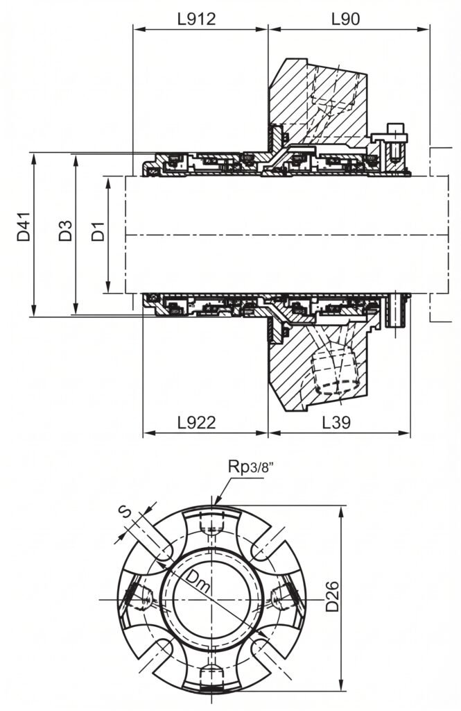
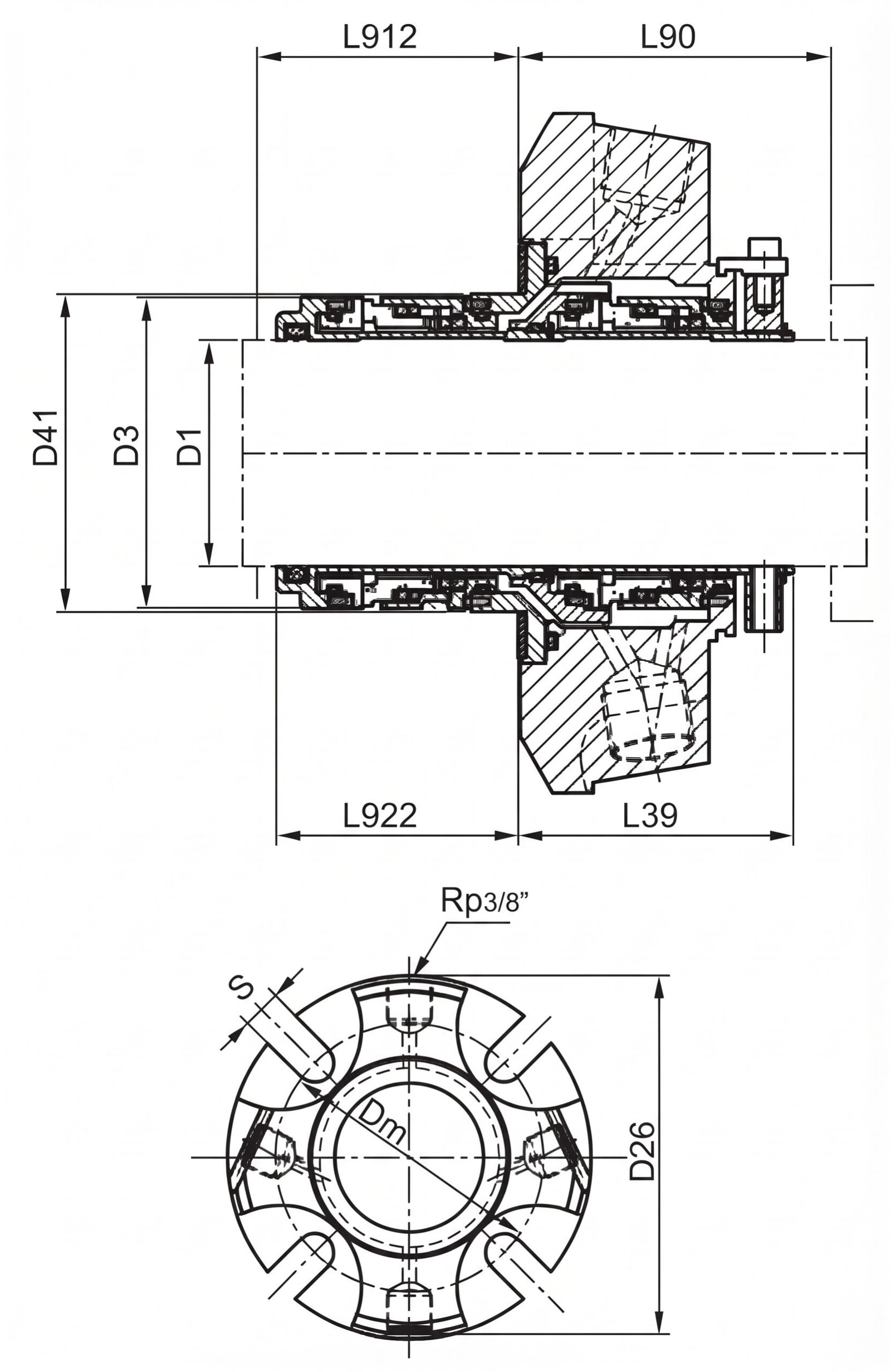
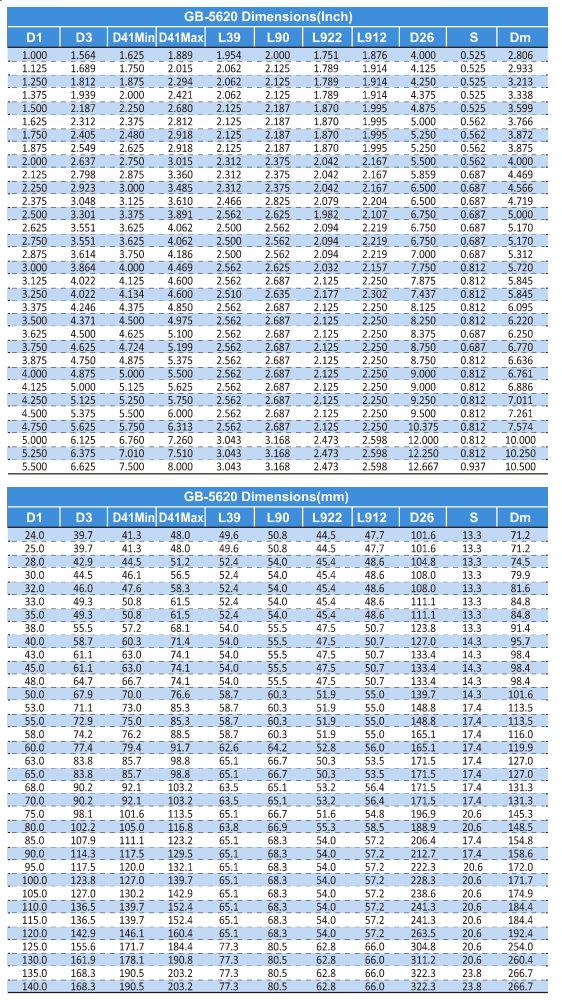
The following reference tables are transcribed from the supplied GB-5620 dimensional sheet. Confirm their applicability to the quoted HJ5620 configuration using the matching assembly drawing.
All symbols are retained as shown in the source, including D41Min, D41Max, L922 and L912. These symbols must be interpreted using the corresponding drawing.
- Metric Dimensional Table — All Dimensions in mm
| D1 | D3 | D41Min | D41Max | L39 | L90 | L922 | L912 | D26 | S | Dm |
|---|---|---|---|---|---|---|---|---|---|---|
| 24.0 | 39.7 | 41.3 | 48.0 | 49.6 | 50.8 | 44.5 | 47.7 | 101.6 | 13.3 | 71.2 |
| 25.0 | 39.7 | 41.3 | 48.0 | 49.6 | 50.8 | 44.5 | 47.7 | 101.6 | 13.3 | 71.2 |
| 28.0 | 42.9 | 44.5 | 51.2 | 52.4 | 54.0 | 45.4 | 48.6 | 104.8 | 13.3 | 74.5 |
| 30.0 | 44.5 | 46.1 | 56.5 | 52.4 | 54.0 | 45.4 | 48.6 | 108.0 | 13.3 | 79.9 |
| 32.0 | 46.0 | 47.6 | 58.3 | 52.4 | 54.0 | 45.4 | 48.6 | 108.0 | 13.3 | 81.6 |
| 33.0 | 49.3 | 50.8 | 61.5 | 52.4 | 54.0 | 45.4 | 48.6 | 111.1 | 13.3 | 84.8 |
| 35.0 | 49.3 | 50.8 | 61.5 | 52.4 | 54.0 | 45.4 | 48.6 | 111.1 | 13.3 | 84.8 |
| 38.0 | 55.5 | 57.2 | 68.1 | 54.0 | 55.5 | 47.5 | 50.7 | 123.8 | 13.3 | 91.4 |
| 40.0 | 58.7 | 60.3 | 71.4 | 54.0 | 55.5 | 47.5 | 50.7 | 127.0 | 14.3 | 95.7 |
| 43.0 | 61.1 | 63.0 | 74.1 | 54.0 | 55.5 | 47.5 | 50.7 | 133.4 | 14.3 | 98.4 |
| 45.0 | 61.1 | 63.0 | 74.1 | 54.0 | 55.5 | 47.5 | 50.7 | 133.4 | 14.3 | 98.4 |
| 48.0 | 64.7 | 66.7 | 74.1 | 54.0 | 55.5 | 47.5 | 50.7 | 133.4 | 14.3 | 98.4 |
| 50.0 | 67.9 | 70.0 | 76.6 | 58.7 | 60.3 | 51.9 | 55.0 | 139.7 | 14.3 | 101.6 |
| 53.0 | 71.1 | 73.0 | 85.3 | 58.7 | 60.3 | 51.9 | 55.0 | 148.8 | 17.4 | 113.5 |
| 55.0 | 72.9 | 75.0 | 85.3 | 58.7 | 60.3 | 51.9 | 55.0 | 148.8 | 17.4 | 113.5 |
| 58.0 | 74.2 | 76.2 | 88.5 | 58.7 | 60.3 | 51.9 | 55.0 | 165.1 | 17.4 | 116.0 |
| 60.0 | 77.4 | 79.4 | 91.7 | 62.6 | 64.2 | 52.8 | 56.0 | 165.1 | 17.4 | 119.9 |
| 63.0 | 83.8 | 85.7 | 98.8 | 65.1 | 66.7 | 50.3 | 53.5 | 171.5 | 17.4 | 127.0 |
| 65.0 | 83.8 | 85.7 | 98.8 | 65.1 | 66.7 | 50.3 | 53.5 | 171.5 | 17.4 | 127.0 |
| 68.0 | 90.2 | 92.1 | 103.2 | 63.5 | 65.1 | 53.2 | 56.4 | 171.5 | 17.4 | 131.3 |
| 70.0 | 90.2 | 92.1 | 103.2 | 63.5 | 65.1 | 53.2 | 56.4 | 171.5 | 17.4 | 131.3 |
| 75.0 | 98.1 | 101.6 | 113.5 | 65.1 | 66.7 | 51.6 | 54.8 | 196.9 | 20.6 | 145.3 |
| 80.0 | 102.2 | 105.0 | 116.8 | 63.8 | 66.9 | 55.3 | 58.5 | 188.9 | 20.6 | 148.5 |
| 85.0 | 107.9 | 111.1 | 123.2 | 65.1 | 68.3 | 54.0 | 57.2 | 206.4 | 17.4 | 154.8 |
| 90.0 | 114.3 | 117.5 | 129.5 | 65.1 | 68.3 | 54.0 | 57.2 | 212.7 | 17.4 | 158.6 |
| 95.0 | 117.5 | 120.0 | 132.1 | 65.1 | 68.3 | 54.0 | 57.2 | 222.3 | 17.4 | 172.0 |
| 100.0 | 123.8 | 127.0 | 139.7 | 65.1 | 68.3 | 54.0 | 57.2 | 228.3† | 20.6 | 171.7 |
| 105.0 | 127.0 | 130.2 | 142.9 | 65.1 | 68.3 | 54.0 | 57.2 | 238.6† | 20.6 | 174.9 |
| 110.0 | 136.5 | 139.7 | 152.4 | 65.1 | 68.3 | 54.0 | 57.2 | 241.3 | 20.6 | 184.4 |
| 115.0 | 136.5 | 139.7 | 152.4 | 65.1 | 68.3 | 54.0 | 57.2 | 241.3 | 20.6 | 184.4 |
| 120.0 | 142.9 | 146.1 | 160.4 | 65.1 | 68.3 | 54.0 | 57.2 | 263.5 | 20.6 | 192.4 |
| 125.0 | 155.6 | 171.7 | 184.4 | 77.3 | 80.5 | 62.8 | 66.0 | 304.8 | 20.6 | 254.0 |
| 130.0 | 161.9 | 178.1 | 190.8 | 77.3 | 80.5 | 62.8 | 66.0 | 311.2 | 20.6 | 260.4 |
| 135.0 | 168.3 | 190.5 | 203.2 | 77.3 | 80.5 | 62.8 | 66.0 | 322.3 | 23.8 | 266.7 |
| 140.0 | 168.3 | 190.5 | 203.2 | 77.3 | 80.5 | 62.8 | 66.0 | 322.3 | 23.8 | 266.7 |
- Inch Dimensional Table — All Dimensions in inches
| D1 | D3 | D41Min | D41Max | L39 | L90 | L922 | L912 | D26 | S | Dm |
|---|---|---|---|---|---|---|---|---|---|---|
| 1.000 | 1.564 | 1.625 | 1.889 | 1.954 | 2.000 | 1.751 | 1.876 | 4.000 | 0.525 | 2.806 |
| 1.125 | 1.689 | 1.750 | 2.015 | 2.062 | 2.125 | 1.789 | 1.914 | 4.125 | 0.525 | 2.933 |
| 1.250 | 1.812 | 1.875 | 2.294 | 2.062 | 2.125 | 1.789 | 1.914 | 4.250 | 0.525 | 3.213 |
| 1.375 | 1.939 | 2.000 | 2.421 | 2.062 | 2.125 | 1.789 | 1.914 | 4.375 | 0.525 | 3.338 |
| 1.500 | 2.187 | 2.250 | 2.680 | 2.125 | 2.187 | 1.870 | 1.995 | 4.875 | 0.525 | 3.599 |
| 1.625 | 2.312 | 2.375 | 2.812 | 2.125 | 2.187 | 1.870 | 1.995 | 5.000 | 0.562 | 3.766 |
| 1.750 | 2.405 | 2.480 | 2.918 | 2.125 | 2.187 | 1.870 | 1.995 | 5.250 | 0.562 | 3.872 |
| 1.875 | 2.549 | 2.625 | 2.918 | 2.125 | 2.187 | 1.870 | 1.995 | 5.250 | 0.562 | 3.875 |
| 2.000 | 2.637 | 2.750 | 3.015 | 2.312 | 2.375 | 2.042 | 2.167 | 5.500 | 0.562 | 4.000 |
| 2.125 | 2.798 | 2.875 | 3.360 | 2.312 | 2.375 | 2.042 | 2.167 | 5.859 | 0.687 | 4.469 |
| 2.250 | 2.923 | 3.000 | 3.485 | 2.312 | 2.375 | 2.042 | 2.167 | 6.500 | 0.687 | 4.566 |
| 2.375 | 3.048 | 3.125 | 3.610 | 2.466 | 2.825† | 2.079 | 2.204 | 6.500 | 0.687 | 4.719 |
| 2.500 | 3.301 | 3.375 | 3.891 | 2.562 | 2.625 | 1.982 | 2.107 | 6.750 | 0.687 | 5.087† |
| 2.625 | 3.551 | 3.625 | 4.062 | 2.500 | 2.562 | 2.094 | 2.219 | 6.750 | 0.687 | 5.170 |
| 2.750 | 3.551 | 3.625 | 4.062 | 2.500 | 2.562 | 2.094 | 2.219 | 6.750 | 0.687 | 5.170 |
| 2.875 | 3.614 | 3.750 | 4.186 | 2.500 | 2.562 | 2.094 | 2.219 | 7.000 | 0.687 | 5.312 |
| 3.000 | 3.864 | 4.000 | 4.469 | 2.562 | 2.625 | 2.032 | 2.157 | 7.750 | 0.812 | 5.720 |
| 3.125 | 4.022 | 4.125 | 4.600 | 2.562 | 2.687 | 2.125 | 2.250 | 7.875 | 0.812 | 5.845 |
| 3.250 | 4.022 | 4.134 | 4.600 | 2.510 | 2.635 | 2.177 | 2.302 | 7.437 | 0.812 | 5.845 |
| 3.375 | 4.246 | 4.375 | 4.850 | 2.562 | 2.687 | 2.125 | 2.250 | 8.125 | 0.812 | 6.095 |
| 3.500 | 4.371 | 4.500 | 4.975 | 2.562 | 2.687 | 2.125 | 2.250 | 8.250 | 0.812 | 6.220 |
| 3.625 | 4.500 | 4.625 | 5.100 | 2.562 | 2.687 | 2.125 | 2.250 | 8.375 | 0.687 | 6.250 |
| 3.750 | 4.625 | 4.724 | 5.199 | 2.562 | 2.687 | 2.125 | 2.250 | 8.750 | 0.687 | 6.770 |
| 3.875 | 4.750 | 4.875 | 5.375 | 2.562 | 2.687 | 2.125 | 2.250 | 8.750 | 0.812 | 6.636 |
| 4.000 | 4.875 | 5.000 | 5.500 | 2.562 | 2.687 | 2.125 | 2.250 | 9.000 | 0.812 | 6.761 |
| 4.125 | 5.000 | 5.125 | 5.625 | 2.562 | 2.687 | 2.125 | 2.250 | 9.000 | 0.812 | 6.886 |
| 4.250 | 5.125 | 5.250 | 5.750 | 2.562 | 2.687 | 2.125 | 2.250 | 9.250 | 0.812 | 7.011 |
| 4.500 | 5.375 | 5.500 | 6.000 | 2.562 | 2.687 | 2.125 | 2.250 | 9.500 | 0.812 | 7.261 |
| 4.750 | 5.625 | 5.750 | 6.313 | 2.562 | 2.687 | 2.125 | 2.250 | 10.375 | 0.812 | 7.574 |
| 5.000 | 6.125 | 6.760 | 7.260 | 3.043 | 3.168 | 2.473 | 2.598 | 12.000 | 0.812 | 10.000 |
| 5.250 | 6.375 | 7.010 | 7.510 | 3.043 | 3.168 | 2.473 | 2.598 | 12.250 | 0.812 | 10.250 |
| 5.500 | 6.625 | 7.500 | 8.000 | 3.043 | 3.168 | 2.473 | 2.598 | 12.667† | 0.937 | 10.500 |
Dimensional Notes
- Dimensions are catalogue references, not approved manufacturing or installation drawings.
- Values marked † require confirmation because they differ from the corresponding original-manufacturer reference supplied for comparison.
- The reference sheet does not list L12. Obtain the complete axial installation dimensions from the matching HJ5620 assembly drawing.
- Metric and inch configurations are separate assemblies and must not be treated as interchangeable solely by unit conversion.
- Confirm all dimensions, tolerances, mounting details and port connections before replacement approval.
Installation Compatibility Checklist
| Installation Item | Information Required |
|---|---|
| Shaft or Sleeve | Diameter, tolerance, surface condition and available length |
| Seal Chamber | Bore diameter, depth and internal clearances |
| Cartridge Envelope | Overall diameter and required axial installation space |
| Gland Mounting | Bolt or stud positions, slot dimensions and mounting clearances |
| Connection Ports | Thread, size, orientation and function of each connection |
| Equipment Movement | Axial movement, shaft runout and alignment requirements |
| Supporting Drawing | Model, size, configuration and drawing revision |
- Dual Seal Arrangement & Support System
Select the seal arrangement together with its auxiliary fluid system. Process pressure, buffer or barrier pressure and differential pressure must be specified separately.
| Arrangement or Requirement | Selection Details |
|---|---|
| Unpressurized Dual Arrangement | Confirm suitability for operation with buffer liquid below seal chamber pressure |
| Pressurized Dual Arrangement | Confirm suitability for operation with barrier liquid above seal chamber pressure |
| Fluid Circulation | Specify circulation method, flow requirements and any pumping-ring configuration |
| Cooling | Determine heat-removal requirements for the operating duty |
| Monitoring | Specify relevant pressure, temperature and liquid-level monitoring |
| Operating Sequence | Define fluid supply and pressure requirements during start-up, normal operation and shutdown |
| Pressure Reversal | Confirm whether the supplied configuration accommodates the anticipated pressure conditions |
Suitability for pressurized or unpressurized operation requires confirmation for the actual supplied HJ5620 assembly.
- Typical Applications
| Application Area | Candidate Equipment |
|---|---|
| Chemical Processing | Compatible chemical transfer and process pumps |
| General Industrial Processing | Suitable centrifugal and circulation pumps |
| Water and Wastewater | Compatible treatment and industrial water-service pumps |
| Pulp and Paper | Suitable process and circulation pump duties |
| Oil Handling | Pumps handling compatible oils and lubricating liquids |
| Other Rotating Equipment | Application-specific installations subject to engineering review |
Suitability depends on fluid chemistry, lubrication, solids content, pressure, temperature, speed and the support system.
Hazardous fluids, abrasive slurries, crystallising media and mixer or agitator installations require a separate application assessment. Food-processing, pharmaceutical and drinking-water duties require documentation applicable to the actual supplied configuration.
- John Crane Type 5620 Replacement Compatibility
The Formax HJ5620 is offered for selected John Crane Type 5620 replacement applications. Confirm dimensional fit, materials, operating limits and auxiliary-system compatibility for the exact installation.
| Existing Seal Reference | Replacement Review |
|---|---|
| Type 5620 | Compare the complete installation dimensions, materials and operating arrangement |
| Type 5620P | Additionally verify pumping-ring provision and circulation requirements |
| Type 5620VP | Additionally verify the seal-head drive configuration and installation requirements |
| Other 5600 Series Variants | Review separately; family membership does not establish interchangeability |
Pumping-ring equipment, reversible seal-head construction and component interchangeability are configuration-specific features. They must not be assumed from the replacement reference alone.
- Standards & Documentation
The supplier lists ISO 3069, DIN 24960 and GB 6556 as reference standards. Confirm the applicable editions, dimensional arrangement and scope of conformity for the selected product.
A standards reference does not establish universal fit across all pump seal chambers. Material certificates, inspection reports, test records and application-specific compliance documents must be agreed before ordering.
- Frequently Asked Questions
| Question | Answer |
|---|---|
| Is HJ5620 a single or dual cartridge seal? | It is specified as a dual cartridge mechanical seal with inboard and outboard sealing assemblies. |
| Is HJ5620 a bellows seal? | No. It is an O-ring pusher configuration. |
| What shaft sizes are listed? | The supplied reference tables cover selected metric sizes from 24 to 140 mm and inch sizes from 1.000 to 5.500 inches. |
| Does HJ5620 include a pumping ring? | Pumping-ring availability and configuration must be confirmed in the quotation. |
| Can every size operate at 21 bar? | No blanket rating is claimed. Confirm the allowable pressure for the selected size, materials and operating arrangement. |
| Can it operate with a pressurized barrier system? | This requires confirmation of the supplied configuration, pressure limits and support system. |
| Is dry running permitted? | Dry-running capability is not established by the supplied HJ5620 information. |
| Does 25 m/s mean 5,000 rpm? | No. Sliding velocity and rotational speed are different quantities. Permissible rpm depends on the relevant face diameter and configuration. |
| Can HJ5620 replace every Type 5620P or Type 5620VP? | These variants require separate verification of their features, dimensions and operating requirements. |
| Are the dimensional tables sufficient for installation approval? | No. Use them with the matching assembly drawing and confirm all installation dimensions and tolerances. |
| What information is needed for a quotation? | Existing seal designation, shaft size, drawings, fluid details, operating conditions, support-system information and quantity. |
- Request a Quote
Need an HJ5620 dual cartridge seal or a replacement for your John Crane Type 5620 installation?
Send the existing seal designation, shaft size, installation drawing or photographs, operating conditions and buffer or barrier system details. Formax Fluid will review the information for configuration selection and quotation.
| Information to Provide | Details |
|---|---|
| Existing Seal | Manufacturer, complete model, size and material codes |
| Equipment | Pump manufacturer and model |
| Installation | Shaft size, seal chamber dimensions and available drawings |
| Process Fluid | Fluid name, concentration and solids content |
| Operating Conditions | Normal and maximum pressure, temperature and shaft speed |
| Auxiliary System | Buffer or barrier fluid, pressure, temperature and circulation method |
| Order Requirements | Quantity and required delivery date |
John Crane and the referenced product designations belong to their respective owners. Formax Fluid is an independent supplier and is not affiliated with or endorsed by John Crane.
Related products
-
Cartridge Mechanical Seals
HR Single Cartridge Mechanical Seals – Replacement for EagleBurgmann HR
Read more